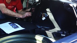
So you’ve just bought yourself a new head unit for, but there’s no ISO wiring harness available to match your car, and you can’t find a wiring diagram for your car.
Fear not, in this video I walk you through some simple techniques to reverse engineer your car’s wiring and get yourself up and running in no time.
NOTES:
In 99% of cases, the wiring on the harness that comes with your new head unit will be colour coded as follows, but always check the diagram that comes with your specific unit.
POWER:
YELLOW – 12V MEMORY – Should have around 12V all the time, even when the car is off.
RED – 12V IGNITION – Should read 0V when the car is off and around 12V when the ignition is switched on.
BLACK – GROUND – Sound be connected to a good quality ground in the car. Some factory car wiring does not have aground wire, and instead uses the shell of the stereo for ground. This works because jsut about everything metal inside your car is ground. If this is the case simply connect this wire to a solid ground inside the car. you can test the continuity between the negative battery post and your entended ground point to and make sure the resistance is minimal.
ORANGE with WHITE trace – ILLUMINATION – Should read 0V when the headlights are off and around 12V when the headlights are on.
BLUE – ANTENNA POWER – Outputs 12V from the head unit to the antenna when the unit is turned on. This is the hardest one to identify on your factory wiring harness on the car side. It will almost certainly be located on the same plug as the wires mentioned above. I normally leave this to last and 9 times out of 10 its the last remaining wire so you know it’s the right one. If not, check to see if the voltage changes when the ignition or headlights are turned on. If it reads 0V all the time and you’ve already identified all your speaker wires, you most likely have the correct wire. to be certain, you can reconnect your factory head unit and set it to radio, then cut the wire and see if the signal drops out or antenna goes down.
BLUE with WHITE trace – REMOTE POWER – This wire can be used to trigger external amplifiers, and typically wont connect to anything on your car’s wiring harness. If your head unit doesn’t have a blue antenna power wire, you can use this wire instead.
GREEN long wire – HANDBRAKE SENSOR – This wire is typically present only on head units that feature video playback. It can be connected to the handbrake sensor wire on your car if you want it to function as intended, or simply splice it in with your black ground wire if you want to be able to watch video with the handbrake off.
SPEAKERS:
WHITE – Left Front (+) Positive
WHITE with BLACK trace – Left Front (-) Negative
GREEN – Left Rear (+) Positive
GREEN with BLACK trace – Left Rear (-) Negative
GREY – Right Front (+) Positive
GREY with BLACK trace – Right Front (-) Negitive
VIOLET – Right Rear (+) Positive
VIOLET with BLACK trace – Right Rear (-) Negitive
SOLDERING TIPS:
- Always use heatshrink to insulate wires, not electrical tape. Use a length of heatshrink double the length of the joint you are insulating.
- Twist your wires together so they are neat and flat with no burring.
- Heat the twisted wires with your soldering iron, THEN run the solder on to the joint. DON’T try to melt the solder on to the wires off the tip of the soldering iron or you will end up with a messy joint and poor quality connection.
Check out more Reviews by Boosted Media
July 30, 2016
OEM+ Audio Sound System Installation
September 7, 2014
BRZ/86/FRS Oil Cooler Install Guide
July 5, 2014


